| home | |
| about us | |
| > | products |
| partners | |
| references | |
| contact us | |
| faq | |
products
Voltage Regulator Adjustment Instructions
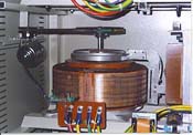
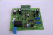
System consists of the parts as below 1. Variac 2. Buck-boost transformer 3. Servo motor 4. Electronic circuit 5. Transformer 6. Microswitch 7. Contactor There is a relay and a red led on the electronic card. When regulator gives normal output the relay remains pulled and the red light is on. If output voltage is higher or lower for any reason, red led will go out; relay will not remail pulled and the contactor will cut output. This is called protection circuit. The regulator can be bypassed by setting the switch on the front side of the regulator to the position 1 (1-0-2) so as not to be without electricity in an urgent situation. There are 4 adjustment pots on the electronic card. There are also 2 sockets on the electronic card. Its easy to be set apart. 1. VOLT ADJUSTMENT When this pot is moved clockwise, output voltage increases. When this pot ismoved just the opposite, output voltage decreases. While servo-motor is making adjustments green & yellow leds on the card flashes. Leds show the direction where The engine rotates. When the fine adjustments are made, the leds fade out. 2. HIGH LIMIT ADJUSTMENT This is the limit for high voltage protection. When the output voltage exceeds this limit, the relay will be off and prevents the contactor from giving output. The standart adjustment is 245 V. If the pot is moved clockwise, the top limit goes higher and vice versa. 3. LOW LIMIT ADJUSTMENT This is the lowest limit for low voltage protection. When the output voltage decrease to a certain point, the relay will be off and prevents the contactor from giving output. The standart adjustment is 190 V. If this pot is moved clockwise, the low limit goes higher and Vice versa. 4. SENSITIVITY ADJUSTMENT If the variac fluctuates & is confused, by the help of this pot oscillation is cut. Motor Stop Keys Servo-motor is not able to turn around about 360° because of its usage. Due to the higher and lower voltage in mains, variac and motor snuggles both sides. In this case there are motor stop keys and diodes to relieve the motors performance. There will be a possibility of changing these parts, if they are exposed to many hits. The motors going to one direction & not coming back indicates motor stop key problems. In three-phased systems adjustment is made by controlling each phase. The relay contactors on the electronic card are series connected and if any of them is off, the output will be cut. When the voltage is given to the regulator for the first time or in a situation lke the electricitys going off and going on, the contactor gives output with delay. In other words it gives output after making fine adjustments. |
|||||
| How it Works | Adjustment Instructions | The Facts When Purchasing | türkçe english |
||||
| siren | |
| document checking system | |
| pathfinder electro-static dust lifter | |
| uninterruptible power supply | |
| blasting machines | |
| blasting machine test device | |
| ohmmeter | |
| rectifier | |
| > | regulator |
| disrupter |


